Products & Services
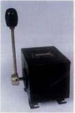
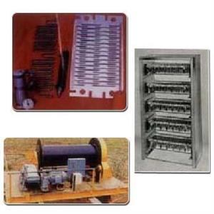
Master Controllers
Cam type, Contacts get actuated by Cams on
operating sequence, shaft to the desired sequence
and are wired to contactor panel. IP41 & IP54
enclosur. Options feature like dead means handle,
spring return and twin controllers can be supplied.
Long Life, Simple Maintenance, Wide Electrical
Clearance.
Size-1 upto 6 contacts.
Size-2 upto 12 contacts.
Size-3 upto 18 contacts.
Size-4 upto 24 contacts.
|
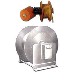
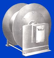
Application The following arrangements show the most common ways of installing the reels. For other applications please consult our technical sales department. |
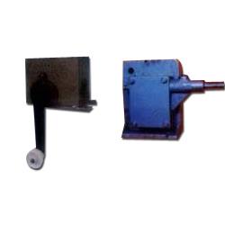
Limit Switches
Roller Level type, Rotary Geared with Ratio 48 : 1 &
60 : 1 No. of contacts up to 4, Rating 10 A. & 40A.
Series Limit Switch up to150 Amp.
The Limit Switch contact block is of high grade
melamine capable of withstanding heavy arcing. The
tips are made of high grade silver cadmium oxide
alloy.
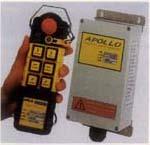
Radio Remote Control
Water / Dust proof IP 65 Strong Casing
Adapts to different applications
Specification :
Sections-assembled push buttons, easy to upgrade
to different models.
Gold plated switches, specially for industrial
used, long stage with high sensivity
PC casing, extremely shock, water, dust proof
Extra-protection : International standard EMS-stop push buttons
Features :
Securitycoad : 256 sets
Output power : Less than 1mW
Frequency Control : Quartz crystals
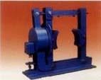
Mill Duty Brakes
- D C Brakes, IPSS/AISE standards,
- Dia 100 mm to 800 mm with breaking torque
- ranging from 6 Kgm. to 700 Kgm.
- Thruster Brakes with Electro Hydraulic Thrusters having thrusts - of 18 Kg 228 Kg
Model No.
Drum Dia
(mm)
Brake Shoe Width (mm)
Thrust Braking (kgs)
Torque (kg mtr)
94-1021
100
57
18
6.0
94-1521
150
70
18
10.0
94-2021
200
88
18
20.0
94-2022
200
88
34
30.0
94-2023
200
88
45
40.0
94-2521
250
108
18
28.0
94-2522
250
108
34
44.0
94-2523
250
108
45
68.0
94-3021
300
127
18
44.0
94-3022
300
127
34
60.0
94-3023
300
127
45
70.0
94-3721
375
152
18
52.0
94-4021
400
152
18
58.0
94-4022
400
152
34
90.0
94-4023
400
152
45
120.0
94-4024
400
152
68
170.0
94-4025
400
152
114
280.0
94-5024
500
190
68
225.0
94-5025
500
190
114
370.0
94-6024
600
228
68
340.0
94-6025
600
228
114
570.0
|
Model No.
|
Drum Dia
(mm) |
Brake Shoe Width (mm)
|
Thrust Braking (kgs)
|
Torque (kg mtr)
|
|
94-1021
|
100
|
57
|
18
|
6.0
|
|
94-1521
|
150
|
70
|
18
|
10.0
|
|
94-2021
|
200
|
88
|
18
|
20.0
|
|
94-2022
|
200
|
88
|
34
|
30.0
|
|
94-2023
|
200
|
88
|
45
|
40.0
|
|
94-2521
|
250
|
108
|
18
|
28.0
|
|
94-2522
|
250
|
108
|
34
|
44.0
|
|
94-2523
|
250
|
108
|
45
|
68.0
|
|
94-3021
|
300
|
127
|
18
|
44.0
|
|
94-3022
|
300
|
127
|
34
|
60.0
|
|
94-3023
|
300
|
127
|
45
|
70.0
|
|
94-3721
|
375
|
152
|
18
|
52.0
|
|
94-4021
|
400
|
152
|
18
|
58.0
|
|
94-4022
|
400
|
152
|
34
|
90.0
|
|
94-4023
|
400
|
152
|
45
|
120.0
|
|
94-4024
|
400
|
152
|
68
|
170.0
|
|
94-4025
|
400
|
152
|
114
|
280.0
|
|
94-5024
|
500
|
190
|
68
|
225.0
|
|
94-5025
|
500
|
190
|
114
|
370.0
|
|
94-6024
|
600
|
228
|
68
|
340.0
|
|
94-6025
|
600
|
228
|
114
|
570.0
|
Electromagnetic Brakes
- Instant Operation
- Maximunm No. of Operations 240
- Requires Stroke Adjustment
- Sizes 100 mm to 400 mm
- Braking Torque - 2 Kgm. to 65 Kgm.
- Disk Brakes for Hoist, with torque rating
- upto 35 Kgm
- Available in single phase 220V, 440V &
- 3 phase 440V
DRUM DIA
50 % RATING
100 % RATING
APPROX POWER
MODEL
TORQUE
MODEL
TORQUE
COSNUMPTION-VA
100
90-10-C1
220
90-10-C2
184
165
150
90-15-C1
760
90-15-C2
650
165
200
90-20-C1
1775
90-20-C2
1500
280
250
90-25-C1
2270
90-25-C2
1930
335
300
90-30-C1
4570
90-30-C2
3880
350
375
90-37-C1
6900
90-37-C2
5860
600
|
DRUM DIA
|
50 % RATING
|
100 % RATING
|
APPROX POWER
|
||
|
MODEL
|
TORQUE
|
MODEL
|
TORQUE
|
COSNUMPTION-VA
|
|
|
100
|
90-10-C1
|
220
|
90-10-C2
|
184
|
165
|
|
150
|
90-15-C1
|
760
|
90-15-C2
|
650
|
165
|
|
200
|
90-20-C1
|
1775
|
90-20-C2
|
1500
|
280
|
|
250
|
90-25-C1
|
2270
|
90-25-C2
|
1930
|
335
|
|
300
|
90-30-C1
|
4570
|
90-30-C2
|
3880
|
350
|
|
375
|
90-37-C1
|
6900
|
90-37-C2
|
5860
|
600
|
Electro Hydraulic Thrustor
Application
"EMC" Electro Hydraulic Thrustor is robust and dependable, possessing the stamina needed for the toughest duty conditions imposed by unattended drives in any industry. Because of its extra-ordinary versatility it has wide applications in electrically driven Hoists, Cranes Elevators, Ropeways, Flap Valves Guillotine Machines, Conveyors, Steel Mills, etc.
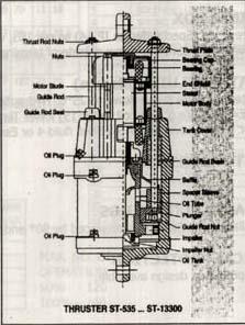
Construction
The "EMC" Electro Hydraulic Thrustor consists of a cylinder filled with oil containing the centrifugal pump located at the bottom and the electric motor assembled on the top cover. The rotor shaft of the motor is extended vertically downwards into the cylinder and carries an impeller at its lower end. The top bearing of the motors are grease lubricated and the bottom bearing is splash lubricated from oil in the tank.
Operation
When the motor drives the impeller, it pumps the oil from the upper to the lower side of the piston. In model 50-2018 Thrustor, the whole motor and assembly move up during power stroke. Inall other models inside the cylinder, above the impeller is a piston with thrust rods connected by a cross bar which delivers the useful thrust. When the power to the motor is switched off, the impeller stops. Oil flows in the reverse direction through the stationary impeller and the load force the piston down.
Features
"EMC" Electro Hydraulic Thrustors deliver gentle thrust without any jerks, consuming very negligible power. It is rated for 100% continuous duty and can withstand many switching operations without over heating the motor. They can be fitted up to 100 from the vertical in either direction due to swivel mounting arrangement.
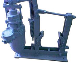
Thrustor Brake
Operation
The braking torque is applied through the action of compression springs that operate the shoes when the current is interrupted. When the current is switched on the shoes is lifted from the drum, the electro-hydraulic thrustor unit acting against the pressure of the springs. The normal position of the brakes is, therefore, 'ON' (shoes gripping the drum), and the brake will return to this position when the current fails.
General Specification
Break Construction
The brakes are robustly made with few and simple working parts, The shoes and base of close grained cast iron and the fulcrum pins are of ground mild steel working in long, reamed bearings. The shoes are fitted with easily renewable woven, fibre, linings held by countersunk rivets, They are adjustable for wear and the pressure exerted by them is easily varid Pivoted shoes are standard on all thrustor-operated brakes.
Thrustors
These are standard electro-hydraulic supplied complete with their first filling of oil. This is 'insulating' oil, Grade 8.30 to British Standard 148, which is readily available at home and overseas. The thrustor cannot be injured by overload or under load.
Windings
All size can be wounded for 3 phase A.C. supplies up to 550 volts and outputs are given here for 50 and 60 C/S supplies. For lower supply frequencies the outputs will be reduced and enquiries should-be referred to us. All thrustors are continuously rated.
Enclosures
All standard units are totally enclosed. Dust seals are fitted as standard, but in extremely dusty situations, or for mounting in the open, a cowl or cover the thrustor is recommended.
Cable Entry
Standard units have tapped ¾ inch BS conduit thread. Supply leads must be flexible to allow free movement, and cables should have 18 inches free length and be not larger than three-core 7/0.029'' to avoid side drag.
Optional Special Features
Manual Release
A level for releasing the brake can be fitted at a small extra cost; this lever is self-resetting.
Hydraulic Over-Ride
Hydraulic control, which enables the brake to be applied by the operator by means of a lever or pedal while the thrustor is energized, can be fitted at extra cost. These brakes can be supplied complete with master and brake cylinder, copper pipe and pedal assembly.
Brake Drums
Brake drums, or drums combined with rigid or flexible couplings, can be supplied to customers' requirements at extra cost. A stout high duty cast-iron drum will be supplied with the brake, if specified. Drums are machined and keywayed ready for fitting to the motor shaft at cost.
Asbestos Linings
Asbestos linings can be fitted to any of the brakes listed in the table. These linings withstand higher temperatures but result in reduced torques, about 0%, because of their lower friction coefficient. They should only used when drum temperatures of over 2200F have to be tolerated and should be the subject of a special enquiry to us.
Choosing The Correct Brake
When selecting a brake from the rating table, opposite, it is important to consider not only the brake torque but also its duty, i.e. its frequency of application and the duration of each stop.
Torque
When a large amount of store energy has to be dissipated or when the stopping times is specified, it will be necessary to caculate the torque from inertias and speeds of the moving parts. For many purposes, however the braking torque can be related to the torque being transmitted. The full load torque of a shaft transmitting a known horsepower is given by:
Torque (lb-ft.) = hp x 5250
rev/min of shaft.
Usually, sufficient will be known about the drive to enable a suitable brake torque to be determined.
Duty
The bake must be chosen with consideration of its intended duty to ensure that the linings will not overheat or wear down too quickly. Selection of a brake for torque only would not ensure this. Since the speed of the drum will also affect the rate at which the drum can dissipate the absorbed energy without overheating. The higher the drum speed for a given torque, the higher will be the rate of energy dissipation in the brake linings during each stopping period the rate being expressible as a horsepower. The column headed 'Nominal horsepower based on linings' in the table is intended as a rough guide to the horsepower of the motor for which a brake is suitable when the duty is equivalent to 'normal' crane duty, i.e. not more than 120 operations per hour continuously applied and with a stopping time not exceeding about one second. If the duty of the brake is less than this 'normal' the horsepower given in the table can be increased. If however, the frequency of application is greater or the stopping time is longer, a larger brake may have to be used; asbestos linings can be fitted and a higher drum temperature accepted with a lower torque. Details of brakes with non-standard features may be obtained from us.
"EMC" THRUSTOR OPERATED BRAKES
AC THRUSTOR-OPERATED BRAKES have a wide application; they can be used with such machinery as electrically driven hoists, cranes elevators, ropeways, machine tools, mixers and laundry machinery.