|
| |
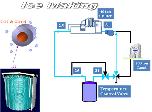
| Thermal Energy Storage |
IceBank thermal energy storage tanks can store renewable energy, like wind and inexpensive night-time electricity, in the form of ice for use during peak demand periods. Reducing the peak electric demand using thermal energy storage can cut cooling costs 20-40%, source energy and emissions are reduced and construction of new power plants and transmission lines can be delayed or eliminated..
BENEFITS OF TES
It reduces operating costs by 25% to 30% because of reduction in demand charges.
It reduces initial costs of chillers, cooling towers, cables, electrical panels and generators.
It uses lower cost, off peak electricity (usually at night) to produce cool energy
|
|
|
|
|
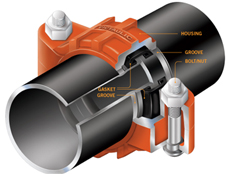
| Grooved Pipe Joining Systems |
Since 1925, Victaulic has been at the forefront of mechanical piping systems innovation, providing numerous patented piping related products that are in use today in multiple markets around the world. And they all stem from one basic concept; the original grooved end mechanical pipe joining system and a steady stem of innovation from Victaulic. The Victaulic grooved end piping system is the most versatile, economical and reliable mechanical pipe joining system available.
Specified for the world's most demanding projects
Grooved pipe joining solutions provides an unmatched competitive edge by reducing installation time, making installations safer and providing design versatility unmatched in mechanical piping systems technology.
By installing Victaulic, conserve time and financial resources through:
Compressed project schedules
Lowered total installed cost
Safer work environment
Install up to 10 times faster than other pipe joining methods.
Requires 45% less man-hours on average over welding
Eliminate costly fire watch and hazardous fumes and flames
Benefits of the grooved systems:
Rigidity
Noise and vibration attenuation
System maintenance and expansion
Flexibility
Seismic stress absorption
Alignment ease
Victaulic offers a complete line of grooved products for 1/2-24"/15-600mm including couplings, fittings, valves and accessories.
Applications:
Chilled cooling water, condenser water, cooling towers, brine systems, special coolant systems, central chiller, ice chiller systems, air handling units, hot (hydronic) heating, boiler piping systems, dual temperature systems, water source heat pumps, fan coils, coil headers, VAV box with hot water coils.
Advanced Groove System (AGS)
The strongest and most dependable mechanical pipe joining system for 14 – 24"/350 – 600 mm diameter pipes.
It starts with a UNIQUE groove:
Wedge shaped for more strength
Wider and deeper than the groove in any comparable system
A Single Groove Profile for all sizes
Formed using standard Victaulic tools and Patent-pending grooving rolls
|
|
|
|
|
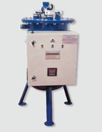
| Cooling Tower Water Treatment |
Addressing Cooling Towers Problems
Where there is a need for cooling water, four factors cause concern for engineers and plant management: Corrosion, Scale, Bio-fouling and Algae Together, they cause major problems including:
Health hazards
Increased electricity and water consumption
Reduction in cooling efficiency
Reduced equipment life expectancy
Until now, the common method of treatment for these problems entailed the use of chemicals which are expensive, environmentally unfriendly and don’t guarantee results.
E.S.T Provides the Right Solution
State of the Art System
The Electrochemical Scale Treatment System (E.S.T) is a state of the art, patented system which prevents scaling, prevents bio fouling, microorganism growth, inhibits corrosion, produces oxidants in the water and prevents the spread of airborne bacteria.
Electrochemical Process
Using a unique electrochemical process, the E.S.T system actively, efficiently and cost effectively deals with the problems associated with cooling water systems without using harmful chemicals.
Multiple solutions and benefits in one system :
Save up to 60% on operational costs:
100% savings on chemicals
20% - 40% decrease in water usage
5% - 15% lower energy costs
10% - 50% reduction in labor costs
Green Technology
No chemical feeds or discharge
Water can be recycled and reused for irrigation
Scale and Corrosion Control
All precipitation of salts occurs in the reaction chamber
No scale in the system heat exchangers
Control over corrosion potential due to low aggression of water
Longer system lifespan
Cooling system works better and longer
Full control and supervision
Performance is monitored with complete control of all parameters
E.S.T – The Electrochemical Process
The E.S.T System is connected to the cooling system or the cooling tower externally so no intervention in system is needed. This significantly reduces installation costs and time. A reaction chamber with electrodes (anodes) installed inside acts as a cathode. The reaction tank is connected to the cooling tower via a circulation pump, and the water is circulated from the cooling tower basin to the reaction tank and back to the cooling tower. Tank anodes are constructed from nickel oxide coated titanium, an exclusive Elgressy patent. DC current passes from the cathode, through the electrolyte (water) in the reaction tank, to the anodes and produces OH ions, which causes a rise in pH near the reaction tank walls. This causes scale to sink to the bottom of the tank, produces corrosion preventing copper and iron ions and creates an environment that prevents the development of harmful micro-organisms. Scale that accumulates on the bottom of the reaction tank is extracted by a pump.
OH+ ions that remain near the anodes cause a decrease of pH levels and produce oxidants which disinfect the water. Maintenance and control of the E.S.T system is performed on site with constant access to all figurers and parameters relating to water quality and system performance online. The Elgressy support team is available to provide on-line support and solutions.
|
|
|
|
|
| Heat Transfer Filtration |
Description / Specification of Heat Transfer Filtration
We are involved in offering a wide range of Heat Transfer Filtration to our most valued clients. Our range of these are widely appreciated by our clients which are situated all round the nation. We offer our range of it at most affordable prices.
We introduce ourselves as an eminent trader and supplier of an extensive array of Heat Transfer Filtration. Prior to dispatch, our quality controllers run numerous tests on the entire range on various parameters of quality and durability. The offered equipment is manufactured using superior quality components with the aid of sophisticated techniques at the vendors' end. Moreover, our precious clients can purchase it in different technical specifications at reasonable price from us within promised time frame.
Features:
Sturdy design
Highly durable
Application specific design
|
|
|
|
|
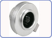
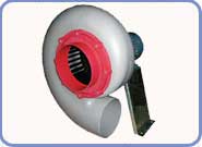
| Centrifugal Impeller |
CIL
• Backward curve centrifugal impeller.
• Speed controllable external rotor motor.
• Compact in size.
• Lighter in weight.
• High efficiency.
• Low sound level.
|
|
|
|
|
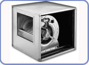
| Centrifugal Fan |
• Double inlet centrifugal fan.
• Forward curved impeller.
• Built In motor.
• Direct driven.
• Insulated cabinet for low noise level.
• Particularly for Air- extraction & Air filtrations system.
|
|
|
|
|
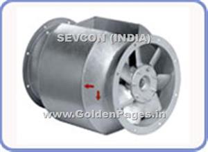
| Bifurcated Axial Fans |
Bifurcated axial fans
• Hot dipped galvanized casing.
• Aluminium die-cast aerofoil impeller.
• Adjustable pitch angle.
• Motors out of the air stream.
• Single phase motors upto 2.2 kw.
• High temperature series for 300 deg/2hrs or 400 deg/2hrs.
|
|
|
|
|
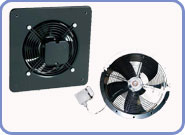
| Wall Mounted Axial Fans |
Speed-controllable.
• Integral thermal contacts.
• Maintenance-free and reliable.
• LW models with Wall plate mounting.
• LR models with flanges for duct mounting.
• Casing and impeller made of GI steel.
|
|
|
|
|
| Ceiling Mounted Fan |
Window/wall/ceiling mounted fans.
• With integral back draught damper.
• Polymide casing and impeller for rust protection.
• Light in weight.
• Sizes 4” to 12”.
|
|
|
|
|
| Chemical Resistant Fan |
Polypropylene(PPH) casing w/o welding joints.
• Injection molded FW wheel made of PPH.
• Direct driven 230v/400v/50hz/60hz motors.
• Motor outside the air stream.
• 3~ motors can be controlled with frequency converter.
• Motor mounting accessories available for different applications.
• ATEX Zone II, category 3 G execution in accordance with
ATEX directive 94/9/CE. (on request).
• Transported air temperature max upto 80 deg C.
|
|
|
|
|
| Natural Turbine |
• The undulating vanes lead to smooth rotation at light wind.
• The bearings at lower and upper position make smooth turns.
• The rotation of the vanes brings the hot air, smoke and wet air
up to the roof and exhausts them out.
• Continuous rotation brings the fresh air regularly for easy ventilation
operation.
• The single rotating mechanism will work for long times e.g. 15
years if not physical damage to turbine.
|
|
|
|
|
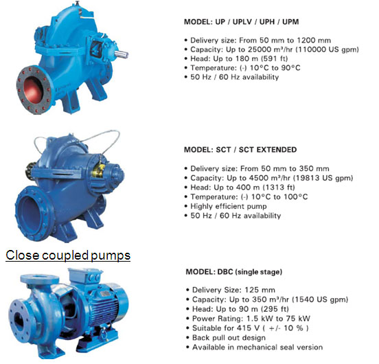
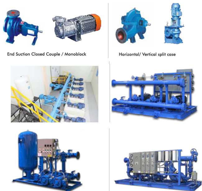
| Suction Pumps |
Pumping System & other Hydronics (HVAC)
The centrifugal pump has long been the workhorse of HVAC systems, supporting the operation of chillers, boilers, cooling towers, domestic water systems, and hydronic distribution systems. And while practically every other component in an HVAC system has been greatly modified to meet ever changing requirements for efficiency and reliability, centrifugal pumps have not changed very much.
That does not mean today’s centrifugal pumps are the same as those of 20 years ago. Manufacturers have made significant improvements in impeller designs, construction materials, bearing and seal designs, and couplings. But these changes have been more evolutionary than revolutionary.
As a result, many managers simply overlook the pump as an opportunity to improve the performance and reliability of HVAC systems. Building designers replicate designs used in the past in new building designs or renovation plans. System operating practices simply follow past tried and true practices. And when pumps fail, technicians replace them with new ones with the same characteristics.
The situation is changing today. Many advances that have affected other areas of building HVAC operation are being applied to pumps and their operation. As a result, engineering and maintenance managers can achieve levels of operating efficiency that were unheard of as recently as 10 years ago. And while improved operating efficiency is a primary benefits of today’s pump installations, it is not the only one. System performance has improved. Reliability has increased. Maintenance requirements have been reduced.
Improving Pump Efficiency
The overall efficiency of any pump used in a building HVAC system is determined by a number of factors, including:
The efficiency of the pump and motor
The efficiency of the pump control
How well technicians maintain the pump and its related components.
|
|
|
|
|
| Fire Fighting Pumps |
Description / Specification of Fire Fighting Pumps
We are involved in offering a wide range of Fire Fighting Pumps to our most valued clients. Our range of these are widely appreciated by our clients which are situated all round the nation. We offer our range of it at most affordable prices.
We introduce ourselves as an eminent trader and supplier of an extensive array of Fire Fighting Pumps. Prior to dispatch, our quality controllers run numerous tests on the entire range on various parameters of quality and durability. The offered equipment is manufactured using superior quality components with the aid of sophisticated techniques at the vendors' end. Moreover, our precious clients can purchase it in different technical specifications at reasonable price from us within promised time frame.
Features:
Sturdy design
Highly durable
Application specific design
|
|
|
|
|
| Dynamic Balancing Cum Control Valves |
INTRODUCTION TO PRESSURE INDEPENDENT SELF BALANCING AND DYNAMIC TEMPERATURE CONTROL & AUTOMATIC BALANCING
Valveautomatic Balancing Systems
What Is Balanced System:
A cooling or heating water distribution system is balanced when the flow in the whole system (through the component lines, distributing and main distributing lines) corresponds to the flow rates that were specified for the design of the system. If the correct balancing of the system is not established, this will result in unequal distribution of the flow so that there will be a surplus effect in some of the terminals, whereas the effect will be inadequate in others. The result of this will be that the required heating/chilling will not be ensured in all parts of the installation. In practice it is not possible to make a correctly balanced system by manipulation of the piping or alteration of the pipe dimensions. Only a correct set of balancing valves can ensure the correct distribution of the flow in the system.
An automatic balancing valve uses the latest flow technology to ensure that the design flow rate is achieved at all times irrespective of any pressure changes with in the system.
Constant Flow:
Until recently constant-flow systems set the standard in HVAC system design. They allow standard designs to be applied to numerous different projects, typically incorporating fixed-speed pumps sized to match the maximum load of the system, These systems are balanced using a proportional method with manually set, fixed-orifice, double-regulating balancing valves installed to account for and reduce the impact of pressure changes in the system. In such constant-flow systems, the capital costs are, indeed, low. However, the energy usage is high, since these systems and the pumps driving them rarely operate at the 100% load they were designed for, calling into question the effectiveness of balancing this type of system in the first place. Further, the process of proportional balancing to commission the system is long, painstaking and expensive.
Variable flow:
Variable-flow systems have risen in popularity primarily because they reduce a system’s energy consumption. They use variable-speed, inverter-driven pumps, the speed of which is changed to match the load. 2-port, motorized control valves are often used to control flows to terminal fan-coil units, or thermostatic radiator valves are used to regulate flow to radiators in heating-only systems. Current solutions in variable-flow systems also include a combination of differential-pressure control valves (DPCVs) which can be used on branches and/or across air-handling units, with double regulating valves to proportionately balance and limit flows to all terminal valves.
However, with both variable- and constant-flow systems, fully automatic balancing can enhance the performance of the HVAC system, eliminating any problems caused by high or excessive system pressures, including noise from the valves and, ultimately, poor control of room temperature. The way the system is balanced will also have a major impact on energy usage, by minimizing pumping costs.
Applications for this type of product include the control of fan-coil units, chilled beams and air-handling units in variable-volume heating and cooling systems and the control of secondary flow on plate heat exchangers. This integrated approach significantly reduces installation and commissioning costs, since the three control functions are specifically matched to ensure optimum system performance and only one valve has to be mounted in the system instead of three. The problem of high and varying pressure drops across traditional 2-port control valves is also effectively eliminated, ensuring a control-valve authority of 100%. It also saves on space, an important concern in, for example, air handling unit installations where the available plant room space for valve installation is often severely restricted.
Applying automatic-balancing technology in constant-flow heating and cooling systems brings advantages too:
Primarily, the use of adjustable flow limiting valves is designed to optimize water flow and can prove invaluable. Such valves provide flow limiting, shut-off and adjustment functions, automatically compensating for changes in system pressure to maximize energy efficiency.
The time and cost of balancing is25 also significantly reduced:
For example, in a typical installation of fan-coil units, manual balancing valves are required at all terminal units, branches, risers and pumps. In contrast, because of their added functionality, automatic balancing valves are only needed at terminal units, reducing the number of valves used, cutting costs and creating a more flexible HVAC system that can be easily adapted or expanded without having to make any new calculations or re-commission the whole system. Indeed, parts of the system can be commissioned and completed in phases, to allow for partial occupation of the building, if required — which can be especially useful in, for example, hotels and hospitals. These adjustable flow-limiting valves are easy to size and set and provide effective flow limitation at terminal units, irrespective of changes in flow and pressure conditions in other parts of the system.
Pressure Independent and Dynamic Temperature Control Valve:
Traditional control valve sizing for constant flow systems involves a Kv calculation, actual pressure drop calculation and a check to ensure minimum valve authority is met. This method is complicated and inflexible, as the changes in design flow, circuit pressure, and required pressure drops can change the required valve, and reduce control-ability. This method also relies on having the correct design information. Pressure independent control valves are used to limit the flow to the fan coil terminal and air handling unit. This flow is not affected by changes in inlet pressure. A diaphragm within the valve keeps the outlet pressure constant, and this delivers a constant flow to the terminal.The added advantage of pressure independent control valves is that, when fitted with an actuator, they replace the manual balancing valve and motorized control valve with a single valve, thus reducing installation cost.
Pressure independent Control Valve Strategy:
Pressure independent control valves can be used with any control system. The actuator options give a choice of thermal, 3-point control, or modulating control. This will work with building management systems and individual room controls, in the same way as traditional control valves. The actuators can also be used to set the valve by limiting flow. In 3-point control applications this can be done using a run time limitation. For example, for 70% design flow we give the actuator 70% of its total run time. With a modulating actuator, to achieve our 70% example we set the controller to control between 0-7v of the 0-10v signal.
Conclusion
The flow rate of a conventional two-way valve depends upon both the degree of opening and the pressure. For example: a valve that is 50% open and supplies 5 GPM at 4 PSI, will at 36 PSI, supply 15.0 GPM at the same opening. When a conventional two-way control valve opens or closes, it causes pressure changes in the system. Often the pressure changes are quite large, and this causes a severe distortion of the valve’s ability to control. When all the valves are open the differential pressure is very low, but as they close the pressure increases more and more. Eventually the full pump pressure exists over the valves. The differential pressure across the valves increases quickly as the flow is reduced. This is due to the quadratic nature of the losses in the pipe, coil and other system components.
The PICCVs are used as a replacement for conventional two-way control valves and will regulate the flow rate regardless of the differential pressure. In other words, it is a true flow controller. It consists of a differential pressure regulator in series with a control valve. The differential pressure is held constant over the control valve. This is what gives a specific flow for each degree of opening, regardless of the differential pressure over the whole PICCV valve. The pressure changes before and after the PICCV valve are absorbed by the pressure regulator, so the differential pressure across the control valve remains constant The flow rate of the PICCV valve depends only on how much the actuator has opened the valve. The actuator modulates the PICCV to a required flow rate, independent of the pressure.
Overflow affects the ability of the control system to achieve the set temperature. It need not be inevitable. Some pressure independent control valves enable fan coils and air handling units to have the maximum flow set exactly at design flow. Switching a traditional control valve to a pressure independent type should not be seen as only benefiting the mechanical contractor, by reducing installation cost. It benefits the systems integrator and most importantly the client, ensuring both improved comfort levels with reduced energy consumption. Pressure independent control valves are an essential part of the hydronic control in chilled water applications. They are simple to select and easy to set. They enable a steady pressure, a steady flow and most importantly a steady room temperature.
|
|
|
|
|
|
|
|
|